Reverse engineering a gift card scrolling display

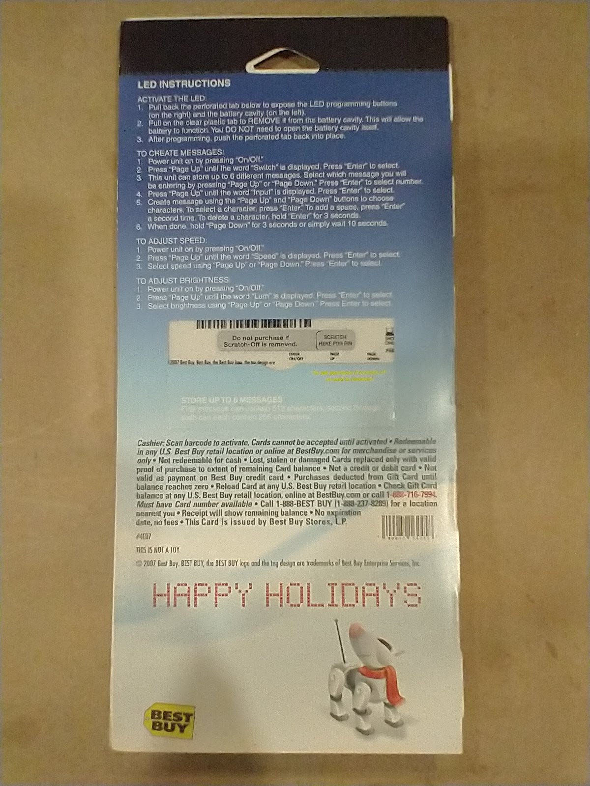
The purpose of this is to reverse engineer a gift card that has a scrolling marquee made out of a matrix of LEDs. The end goal of this is to eventually get a display that can be connected to a microcontroller. These gift cards were acquired around 2007 by purchasing them with small amounts of money on them.

Tools Used:

Test setup:

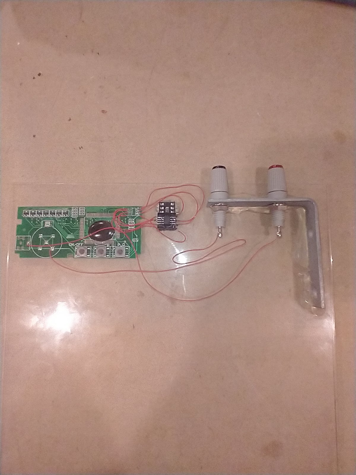
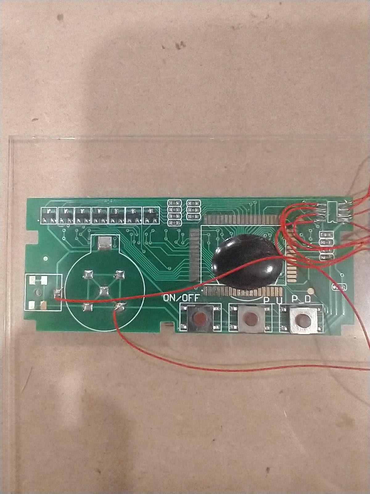
A hot air soldering gun was used to remove the EEPROM. EEPROM was then soldered to a 8 pin SOIC to DIP socket breakout. Device PCB had fly wires attached to a 8 pin dip socket so the EEPROM could be removed during device reverse engineering and socketed into the TL866II reader/programmer.

Reverse engineering steps:

  1. Take backup of device EEPROM before starting (do not brick it)
  2. Power up device and modify using built in buttons, make sure to notate what was modified
  3. Power down device, remove EEPROM and read EEPROM using TL866II reader/programmer
  4. Save EEPROM reading as a hex dump, at this point it can be diffed using a tool like kdiff3 to compare to previous dumps
  5. go to step 1.

If at any point the system gets bricked it was possible to re-flash using image taken in step zero. This tended to happen when the device was operated in ways the user could not interact with. For example the device allows for changing the message scrolling speed with a value between 1 and 6, setting this to say 15 decimal using the programmer causes the device to output garbage.

Notes on how the device memory is mapped and behavior:

Device appears to have multiple different message storage locations. This mostly focuses on “message 1” but it should be trivial to figure out the other locations.

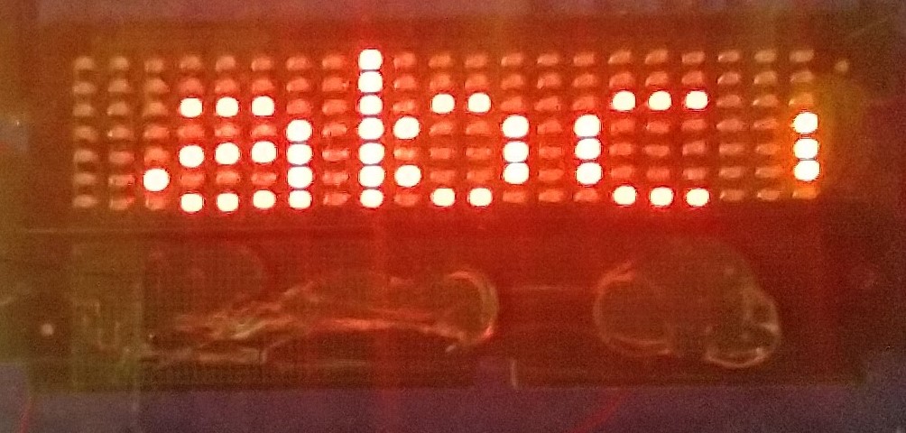
The message length for message 1 is stored at 0x11. The value is in hex. For the example below the device would display the entire alphabet in lowercase. The message starts at 0x100. The message length can be set to the full 0xFF value and the gift card will display it.

The gift card also allows for speed selection. This is set at 0x28. The value can be between 0x01 and 0x06 any value over 0x06 makes the badge crash and print the character it represents for 0x255 .

For some reason the badge does not quite map to the ascii table, for example 0x41 should be an uppercase A but instead it prints as a lowercase a. To decode a letter mapping it is fairly easy to set the message up to contain it and see what hex value it is mapped to. The uppercase letters start with A at 0x21 and increment through the alphabet upwards.

Future uses:

If the device and EEPROM power were separated and the EEPROM was multiplexed using a digital switch it should be possible to use this as a display for a microcontroller.

High availability Pi-hole cluster with Nginx load balancing

This is a quick write up for the hardware and software config for the high availability Pi-hole cluster with Nginx load balancing.

Hardware:

List of components used:

Name Part Number Quantity Link
raspbery pi single board computers (with cases and SD card) 3
USB A male to micro usb cables 3 https://amzn.to/2x9OdK6
6″ Ethernet patch cables 4 https://amzn.to/2KCi7K4
gigabit switch that has 5V input AM-SG205 1 https://amzn.to/2VGYGGy
5V 10A amp power supply Mean Well LRS-50-5 1 https://amzn.to/3aFPkic
Wire https://amzn.to/2Y2wv6q
Crimp ferrules https://amzn.to/3aH4a8c
Double Stick tape https://amzn.to/35eHUSg
panel mount Ethernet connector 1 https://amzn.to/2VGYMOq
usb to power PCB 2 Order from OSH Park
dupont female to female connector (for display) 18 https://amzn.to/3cPOkKa
PiOLED 0.91inch 3 https://amzn.to/2zyjJlV
1U rack mount case

Setup notes:

To configure the load balancer:

Add this to nginx.conf (make sure to change IPs to match your two pihole pi)

stream {
upstream dns_servers {
server 192.168.1.136:53 fail_timeout=60s;
server 192.168.1.152:53 fail_timeout=60s;
}
server {
listen 53 udp;
listen 53; #tcp
proxy_pass dns_servers;
error_log /var/log/nginx/dns.log info;
proxy_responses 1;
proxy_timeout 1s;
}
}

to restart nginix run this:

sudo /etc/init.d/nginx restart

See this page for details https://www.nginx.com/blog/load-balancing-dns-traffic-nginx-plus/

WS2812b Led Ring Christmas Tree

This tree design is based on the tree featured here: https://hackaday.io/project/18821-ws2812-christmas-tree

My plan was to cut the tree out on my CNC machine using a single fluted endmill. After shattering a couple of sheets of acrylic this idea was abandoned. The design file was sent to https://www.ponoko.com/ for laser cutting. The design fits into a P1 sheet and was cut using 0.118 inch clear acrylic. Here is the design file that can be uploaded to be cut: https://github.com/mdunakin/Ws2812bChristmasTree/blob/master/Design/tree5.svg

The code is just a configured version of the FastLED DemoReel1000 example code. It can be found here: https://github.com/mdunakin/Ws2812bChristmasTree

Construction was not super complex. The two tree pieces were hot glued together. The led rings were attached from smallest to largest. When the ring was attached it was wired with 30 awg wire wrap wires. The ground and vcc on the rings were connected together. The data out on the rings was connected to the next rings data in. As a small side note these wire strippers are amazing if you want to strip wire wrap wire https://amzn.to/2SaPNAG

Here is a picture of the constructed tree:

IMG_20181208_162236

Here is a video. The tree looks much better in real life.

https://www.youtube.com/watch?v=gBCcFjnqSJw

Solar Powered ESP8266 Wemos D1 WIFI sensor node for Domoticz using ESPEasy

This post will cover building a low power solar WIFI sensor node using a Wemos D1 module. The module is loaded with ESPEasy firmware and reports sensor data to a Domoticz server.

The sensor nodes can be used with any of the sensors the ESPEasy firmware can support. This includes temperature, moisture and a host of other physical and environmental inputs and outputs. A full list is located here: https://www.letscontrolit.com/wiki/index.php/Devices

Hardware:

Bill of materials:

Description Notes Qty
JST-XH 2 Pin Header Male 2
JST-XH 2 Pin Pigtail Female 3
1N4004 Diode 1
.1″ Header Female (8 Pin) 2
.1″ Header Male (8 Pin) 2
.1″ Header Male (2 Pin) For Sleep 1
.1″ Header Male to Female (8 Pin) 2
TP4056 DW01A Charger Board Module 1
Mini 12-cell Polycrystalline Solar Panel 6V 1
18650 or other lithium ion Battery 1
Wemos D1 1
Wemos D1 Mini LiPo Battery Shield 1
Heatshrink for battery wires 1
Dry Box 135*80mm*40mm 1
Optional PCB Gerber Link Below 1
Optional Target Sensor 1

The first two versions of this sensor node were built by hooking  .1″ headers together and fixing all the components inside a large dry box with double stick tape. Here is a photo of the first two versions:

These versions were somewhat time consuming to reproduce so a PCB was spun to help speed up build times.

KIMG1721

Here is a link to the gerbers: https://github.com/mdunakin/PCB/tree/master/WemosD1Plate

This PCB takes power in from a solar cell on the left JST-XH connector. This is fed through a 1N400X diode that is acting as a bypass diode. This then feeds into the Blue PCB shown at the top. This PCB acts as a charge controller. Ideally the charge controller on the Wemos D1 mini LiPo battery shield could be used but it lacks over discharge protection. This is the reason for the secondary charge controller. The left JST-XH connector is used to attach the LIPO battery and the red and black wire are fitted with a female JST-XH connector that plugs into and powers the Wemos D1 mini LiPo battery shield.

JP2 and JP3 are used to break out the IO pins on the Wemos D1 mini. The sleep jumper allows for the Wemos D1 to be put into a deep sleep mode conserving battery power. The sleep function is documented here: here: https://www.letscontrolit.com/wiki/index.php/Devices

KIMG1806

Configuration:

Before getting sensor readings you will need to get a copy of Domoticz from here: https://domoticz.com/ I recommend running this on a computer that will be on all the time and also running it as a Windows service.

You will also need to flash your Wemos D1 with the ESPEasy firmware https://www.letscontrolit.com/wiki/index.php/ESPEasy This was a simple process. You just grab the installer from the link above. Run the executable and point it at the correct serial port.


Hardware Configuration:

The hardware configuration can be broken down into two main parts. Configuring the ESP8266 to send the data and configuring the Domoticz server to receive the data.

Before configuring the sensor it needs to be created in Domoticz to get the IDX number so the ESP8266 knows where to send the data.

This is done by adding “dummy” hardware in Domoticz and then selecting the “create virtual sensors”  button.

Domo2

After that create a “Temp+Hum” sensor:

Domo6

Here is the configuration for the ESP8266 using ESPEasy firmware:

DHT22

Make sure that the Domoticz server is configured on the ESP8266:

WemosServer

Battery Monitor:

Battery voltage monitoring is described here:

https://arduinodiy.wordpress.com/2016/12/25/monitoring-lipo-battery-voltage-with-wemos-d1-minibattery-shield-and-thingspeak/

Here is a setup screen on ESPEasy:

AnalogAdc

Here is the corresponding Domoticz setup:

Create a dummy Hardware device:

Domo

Click the create virtual sensors button

Domo2

Add a voltage sensor

Domo4


Sleep:

To get ESPEasy to sleep, configure each configured device to take readings at the interval you desire on the devices tab. Then under the config tab set the interval.

Domo5

After that cut power by disconnecting the battery and solar cell and set the sleep jumper on the PCB and re-power up the system. If everything is configured correctly the device will now sleep between readings. Note, when first powered up the ESP8266 will have a responsive web server for 30 seconds before going to sleep.

Here is some data that was collected from a previous sensor deployed during summer:

WemosTest2WemosTest

The PCB assembly and battery are packaged in a small dry box with a solar cell mounted to the lid. The DHT 22 will be placed into a Stevenson Screen that was purchased from: http://www.misolie.net/plastic-outer-shield-for-thermo-hygro-sensor-spare-part-for-weather-station-transmitter-thermo-hygro-sensor-p-515.html

KIMG1814

KIMG1810

Binary Compare Game

As a kid one of my favorite book series were Forrest Mims Circuit Scrapbooks. They were interesting to read and build the circuits out of. One of the projects that was in my opinion the most fun to play with is a binary guessing game from The Forrest Mims Circuit Scrapbook, Vol 1 page 121. Since prototype PCB prices have dropped recently due to competition in China this was a project that seemed interesting to convert to a PCB.

Schematic:

Capture

Changes to above schematic:

  • A 10K pullup was added to the 74193 side of S1 to prevent noise from loading new numbers to guess.
  • A .1 μF bypass cap was added to the 555 timer to prevent ringing in the output.
  • The circuit is powered by a 9V battery. This battery goes to a switch. After the switch a LM2596 buck module is used to drop the voltage down to 5V

Gerbers:

https://github.com/mdunakin/PCB/tree/master/BinaryCompare

Photo of finished PCBA:

KIMG1401


Door Ajar Sensor

This project was created to address an issue with the layout of my house. The door from the garage into the house overlaps with another door. If this door is left open it could get hit by the overlapping door. To prevent this from happening a visual indicator was installed to show if the overlapping door is left open.

Circuit:

Schematic

VCC is supplied by four AA batteries. The circuit is broken down into two parts. On the left is a circuit that shows if the door is open. On the right is a low battery indicator.  LED2 is a flashing led. This part was selected to lower current draw versus an always on led. U1 is an open collector voltage sensing chip that triggers at 3.6V.

Gerbers and BOM for the PCB can be found at:

https://github.com/mdunakin/PCB/tree/master/DoorAjar

Photos of completed and installed circuit:

Garden Time lapse with Security Camera

The goal of this was to get a long term time lapse of my garden growing each season using off the shelf hardware. The camera used for this is a SV3C SV-B01-1080PL bullet camera powered with POE.  The camera is mounted outside with a fixed view of the garden. At the start of this project a new gmail account was acquired to be used with only this camera. The email section of the camera was configured and tested. Then then camera was configured to send an image every hour to the above mentioned gmail account.

CameraConfig1

To date this has resulted in eleven thousand plus emails with photos. Manually downloading and extracting the photos seemed like a tedious and boring  process so a different route was found using the Thunderbird mail client. The client was installed and configured to use the gmail account. Then the attachment extractor extension was added.

attachment

This extracted all the attachments to a folder. The extracted images had varying degrees of brightness so the output folder was batch processed using  PhotoScape.

Capture

After the batch processing was done the group still contained images that happened during night times or photos with excessive shadows. Luckily the output files had a similar file nameing structure so a simple C# program was written to move and re-name photos shot during specific times of day. The paths will need to be tweaked to run it on a different system. Here is the code:

using System;
using System.IO;

namespace PhotoCleaner
{
    class Program
    {
        static void Main(string[] args)
        {
            try
            {
                var folderLoc = @"C:\Users\media2\Desktop\New folder";
                var destFolderLoc = @"C:\Users\media2\Desktop\Output";
                var directoyInfo = new DirectoryInfo(folderLoc);
                var Files = directoyInfo.GetFiles("*.jpg");
                var counter = 1;
                foreach (FileInfo file in Files)
                {
                    Console.WriteLine(file.Name);
                    //file.Name = "IMG_chn0_TIMER_MNG_20170522164542_001.jpg"
                    var fileName = file.Name.Trim();
                    fileName = fileName.Replace("IMG_chn0_TIMER_MNG_", "");
                    var year = fileName.Substring(0, 4);
                    var splitFileName = fileName.Split('_');
                    if(splitFileName.Length == 2)
                    {
                        var rawDate = splitFileName[0];
                        var hour = rawDate.Substring(8, 2);
                        var hourInt = int.Parse(hour);
                        if(hourInt = 16 && year == "2018")
                        {
                            File.Copy(Path.Combine(folderLoc, file.Name), Path.Combine(destFolderLoc, $"frame{counter.ToString().PadLeft(4, '0')}.jpg"));
                            counter = counter + 1;
                        }

                    }
                }
            }
            catch (Exception ex)
            {
                Console.WriteLine(ex.ToString());
                Console.ReadLine();

            }
        }
    }
}

After running the above code a folder with files named frame0001.jpg, frame0002.jpg… should be generated. To stitch the files together FFMPEG was used. After installing FFMPEG it was added to the system path. This blog helped figure out the different flags that needed to be set in FFMPEG http://notes.theorbis.net/2010/05/creating-time-lapse-with-ffmpeg.html The parameters suggested in the blog post were tweaked slightly to end up with this:

ffmpeg -r 12 -i frame%04d.jpg -qscale 0 -s hd720 -vcodec libx264 -preset fast -crf 25 OUTPUT.MP4

Here are the results:

2018 (short):

2017-2018 (long):

Improvements:

The above C# code could be improved by accounting for sunrise and sunset values in the time calculations. This should account for the sun shifting in other seasons and make the video have less of a strobe like occurrence from shadows.

Using ke5fx HP 7470 plotter emulator with a 54659B module on a 54600B oscilloscope

This write up will talk about modifying the ke5fx HP 7470 plotter emulation software to work with a 54600B oscilloscope using Microsoft Windows.

NOTE: make sure to use a null modem cable

Steps to setup computer:

      1. Get a working serial port on your computer with a USB to serial converter or a native serial port.
      2. Download the ke5fx software from: http://www.ke5fx.com/gpib/7470.htm
      3. Modify default_connect.ini Comment out the top line and add the second line (Make sure your com port is correct):
        ;interface_settings GPIB0
        interface_settings com3:baud=19200 parity=N data=8 stop=1

        also modify:
        is_Prologix 1
        To
        is_Prologix 0
      4. On the 54600B go to the print menu and make sure the scope is in DTR mode, also make sure the scope is set to 19200 baud.

Steps to print image to computer:

  1. Make sure that the com port your device is on matches the default_connect.ini file. If it does not then edit the file or use the device manager to change the assigned to serial port mappings.
  2. In the ke5fx 7470.exe software choose this option:scope1
  3. Press print screen on plotscope

Hydroponics Update Part 3

KIMG0610

To understand the context of this post you may want to read updates one and two.

The half gallon mason jars worked well as shown with the romaine growing in the photo above. The jars started developing hairline cracks in the bottoms that started leaking.  This was more than likely due to routine handling during weekly water changes. This lead to attempting to find a plastic substitute for the mason jars.  The jars that were selected were a 96 ounce petg plastic container with a handle. These were prepared with a net cup similar to the process in post two. After a few months of growing an algae problem occurred in the jars. This is probably due to the high nutrient levels and bright lights the plants are grown under. A test is being conducted to see if painting the jars black will help combat this problem. Below is a photo of basil grown in the garden vs hydroponic basil grown in the new containers. The basil was started by cloning a basil plant purchased in the supermarket. The grow medium was rock wool.


KIMG1203